This guide walks you through removing and refitting the LTO drive in a SymplyPRO LTO Desktop unit fitted with a Version ‘C’ chassis. Refitting the replacement drive is a straightforward reversal of the removal steps.


TABLE OF CONTENTS

Overview

The LTO drive inside a SymplyPRO LTO Desktop unit is a field-replaceable module. If Symply Support has diagnosed a drive fault and supplied a replacement, you can swap the drive yourself using the steps below - no specialist tools are needed beyond a suitable screwdriver. The whole procedure takes around 15 minutes.

These instructions apply specifically to the Version ‘C’ chassis. If the underside of your unit does not match the photographs in Step 1, stop and contact Symply Support to confirm your chassis version before going any further.


Before you start

  • Power the unit down and disconnect the power and data cables.
  • Have your replacement drive ready and a suitable screwdriver to hand - we use a Philips PH2.
  • Work on a clean, flat surface - the foam packaging the unit shipped in makes a good work mat.
  • Read all eight steps and look over the photographs before you begin.
Steps 5–8 (refitting the replacement drive) are a reversal of the removal steps 1–4. It helps to keep the screws from each stage together and note where they came from.

Step 1 - Remove the cover plate screws
1
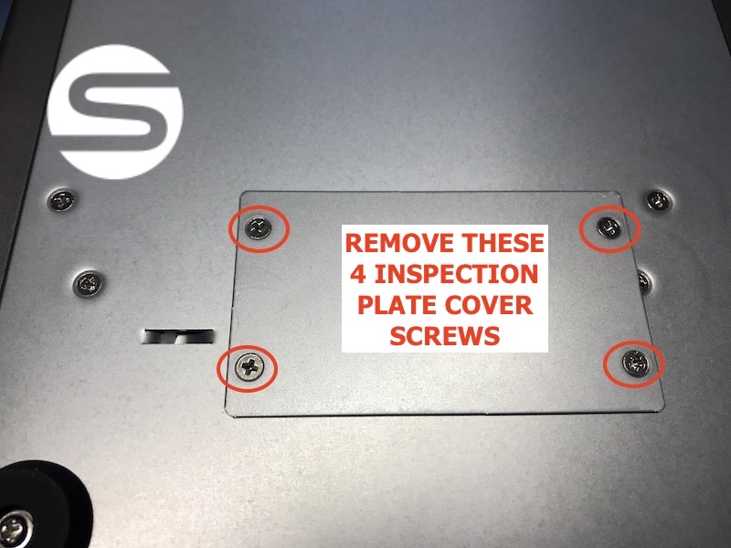
Turn the unit over. On the underside you’ll find the inspection panel, held in place by four screws. Remove all four to release the cover plate.
Underside of the SymplyPRO LTO Desktop unit showing the inspection panel with the four cover plate screws circled in red
Remove these four inspection plate cover screws.
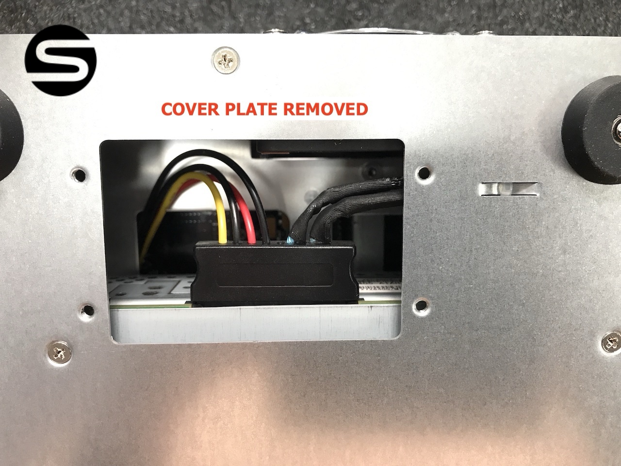
The inspection panel with the cover plate removed, exposing the drive connector and cabling inside the chassis
With the cover plate removed, the drive connector and cabling are now accessible.

Step 2 - Disconnect the drive connector
1
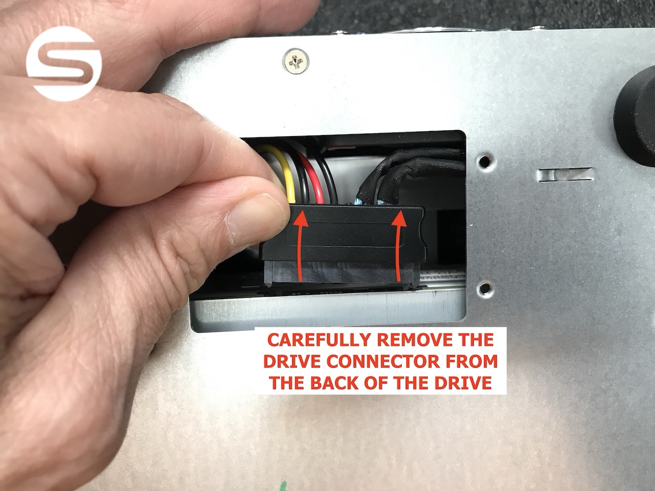
Reach in through the inspection panel and carefully pull the connector away from the back of the drive. Grip the connector body rather than the cables, and ease it straight off.
A hand reaching into the inspection panel to carefully unplug the connector from the rear of the LTO drive
Carefully remove the drive connector from the back of the drive.

Step 3 - Remove the three drive securing screws
1
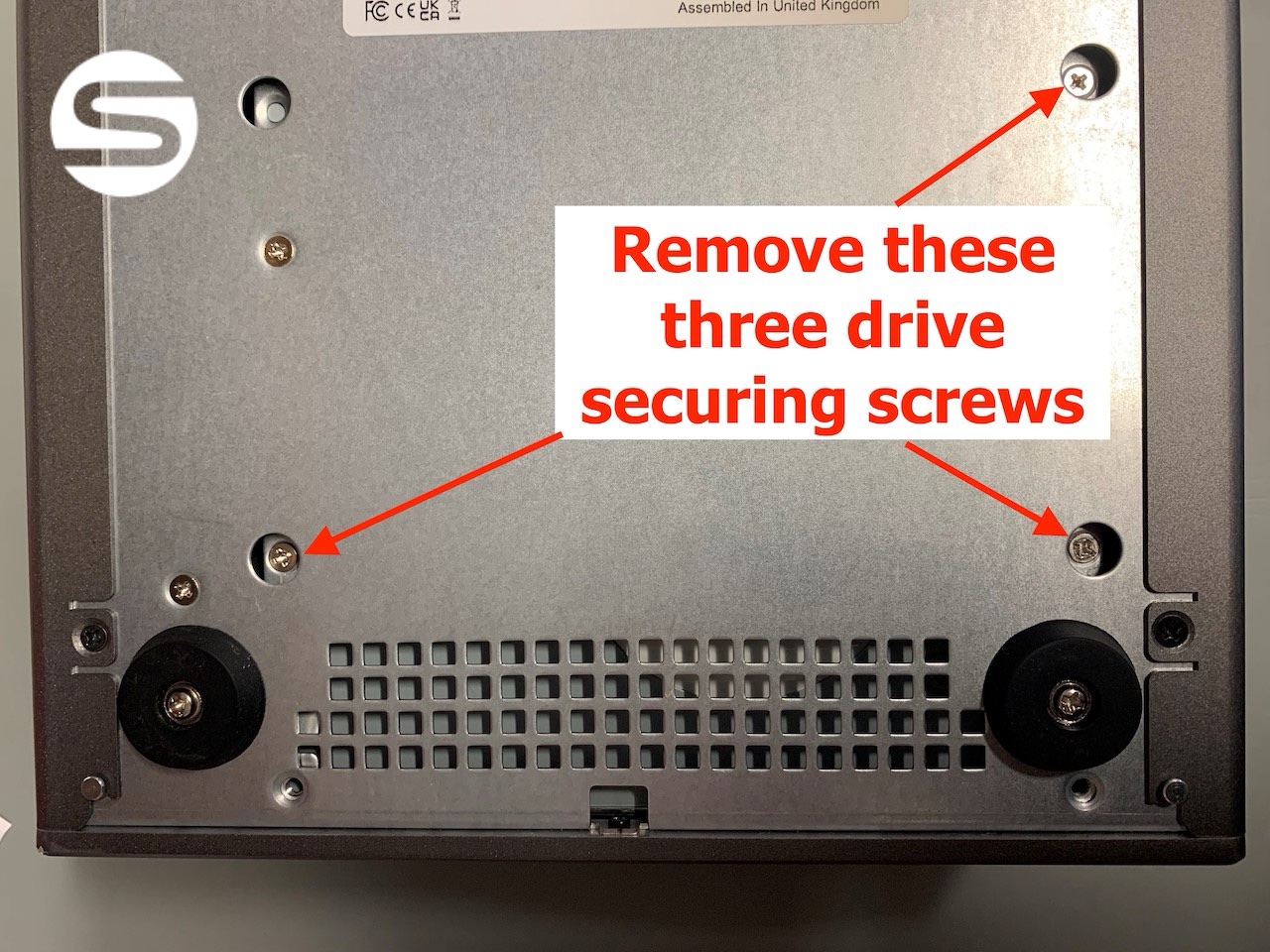
Still working on the underside, remove the three screws that hold the LTO drive in place within the chassis.
Underside of the chassis with the three LTO drive securing screws indicated by red arrows
Remove these three drive securing screws.

Step 4 - Slide the drive out of the chassis
1
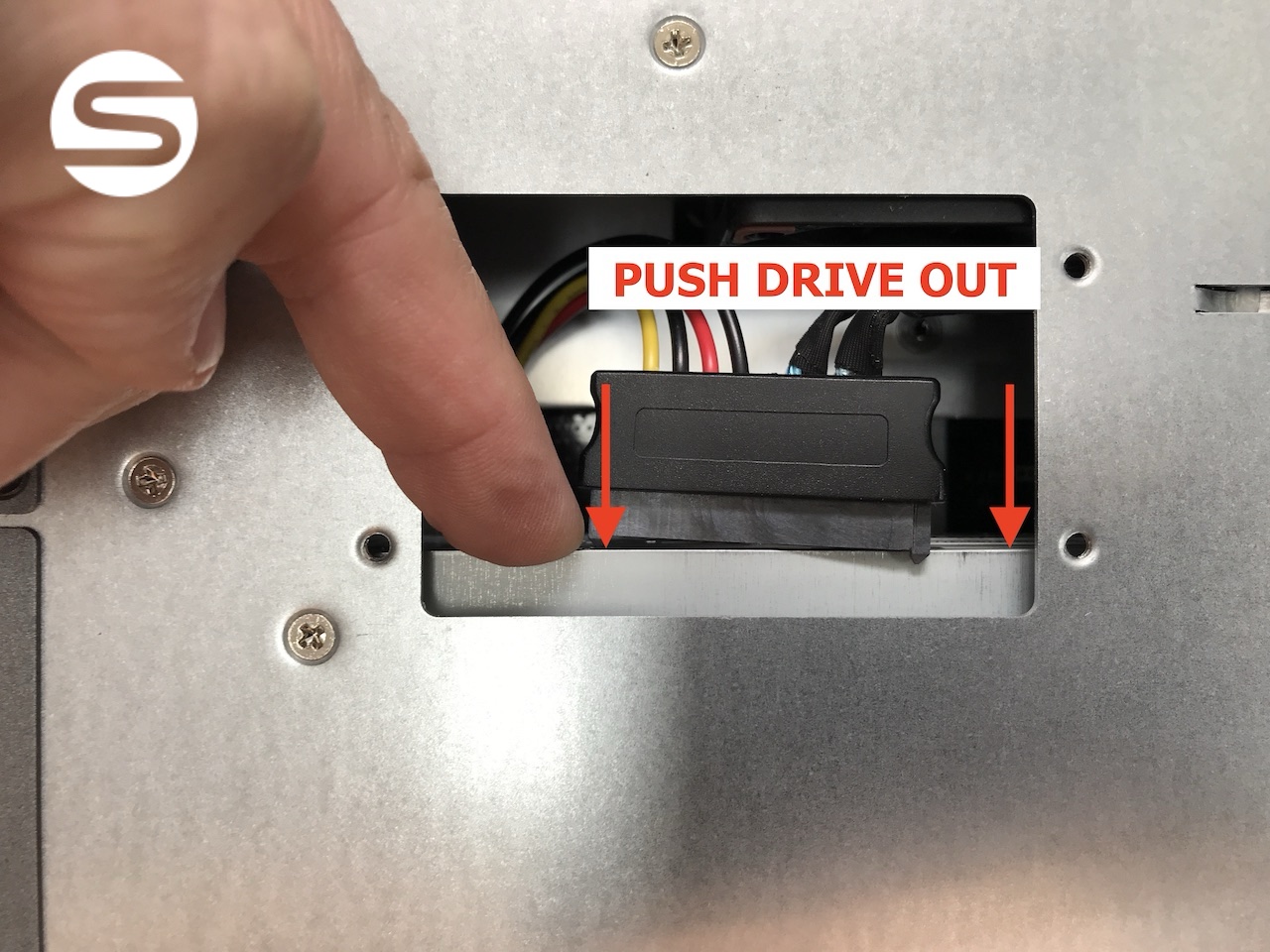
Gently push the back of the drive from inside the inspection panel to start it moving.
A finger pushing the rear of the drive outward through the inspection panel to free it from the chassis
Push the drive out from inside the inspection panel.
2
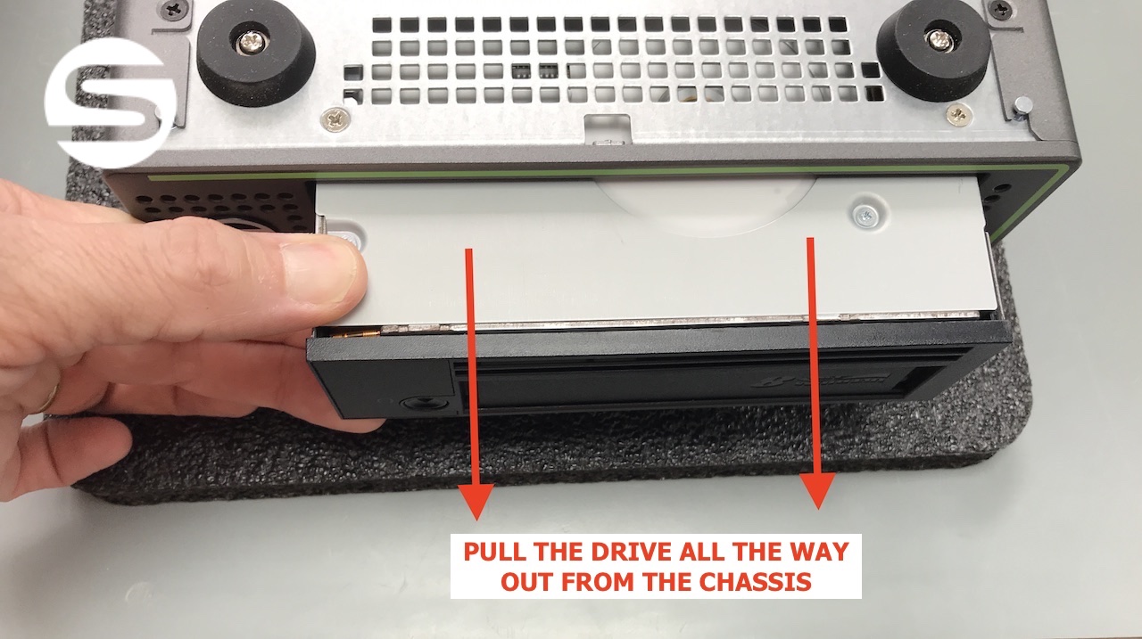
Once it starts to move, draw the drive all the way out from the front of the chassis.
Pulling the LTO drive fully out from the front of the chassis
Pull the drive all the way out from the chassis.
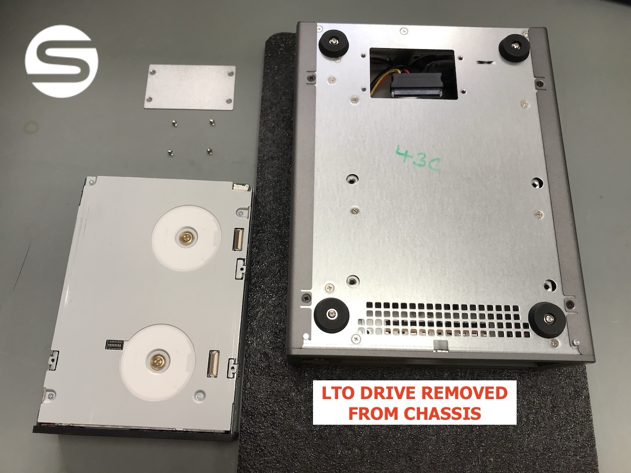
The LTO drive fully removed and sitting beside the empty chassis
The LTO drive removed from the chassis.

Step 5 - Fit the replacement drive

1
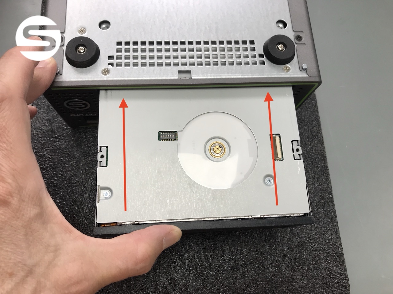
Slide the replacement drive into the chassis from the front. Seat it fully so the mounting holes line up with the screw holes in the chassis. This is a simple reversal of Step 4.
Sliding the replacement LTO drive back into the chassis from the front
Slide the replacement drive into place.

Step 6 - Reconnect the drive connector
1
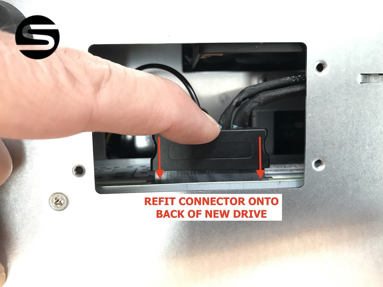
Refit the connector onto the back of the new drive, pressing it home squarely until it is fully seated.
Refitting the connector onto the rear of the newly installed drive through the inspection panel
Refit the connector onto the back of the new drive.

Step 7 - Check the wiring is clear of the fan
1
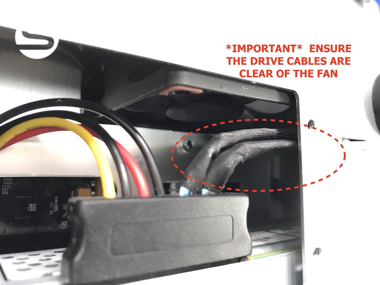
Before closing up, confirm the drive wiring is routed clear of the rear fan blades.
Ensure the drive cables are clear of the fanCables fouling the fan can cause noise, restrict airflow, and lead to overheating or damage. Take a moment to route the wiring away from the fan before refitting the screws and cover plate.
Interior view showing the drive cabling routed clear of the rear fan, with the fan area highlighted
Check that the drive wiring is clear of the back of the fan.

Step 8 - Refit the screws and cover plate

1
Refit the three drive securing screws, then reattach the inspection panel cover plate with its four screws.
2
Reconnect the power and data cables, power the unit back on, and confirm the new drive is detected by your host and diagnostic software.
Replacement completeThe replacement LTO drive is now fitted. If the new drive is not detected once the unit is powered back on, re-check the connector from Step 6 is fully seated before submitting a support ticket.

If you have any questions please submit a [support ticket]